fumanchu182
3000 Posts Club
Vendor
Premium Account
U.S. Navy Veteran
Donating Member
9 Second Best E/T
HFCOTM
- Member ID
- #2366
- Messages
- 3,761
- Reactions
- 9,256
- Likes
- 302
- City
- Pasadena
- State
- MD
- Country
- United States
- Vehicle
- 2015 Challenger SRT Hellcat
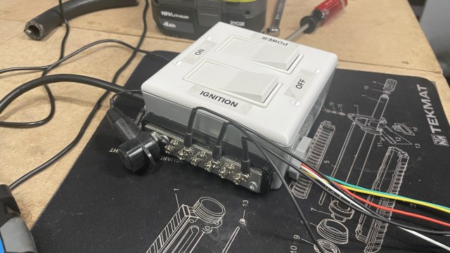
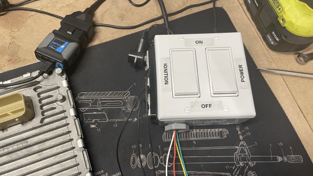
So I decided to build a bench harness for Dodge PCMs. I have all the free time in the world now that I have separated from the Navy and here is my adventure so far. Lets start with some components that I will be using. I decided to go with this power supply, it has 12V DC and comes with a terminal end, which will make it easy to work with: https://www.amazon.com/dp/B07C75RT38?psc=1&ref=ppx_yo2_dt_b_product_details. For the enclosure we are not doing anything fancy, only HomeDepot's finest will do. https://www.homedepot.com/p/BELL-We...ded-Outlets-White-2-Gang-PDB77550WH/316300308 topped off with a https://www.homedepot.com/p/Leviton...ker-Wall-Plate-1-Pack-R52-80409-00W/100048406 and two switches: https://www.homedepot.com/p/Leviton...t-Rocker-Switch-White-R62-05693-2WS/100162432. For the outside ground bus I choose the following from Autozone: https://www.autozone.com/miscellane...nduct-tite-black-universal-bus-bar/476883_0_0
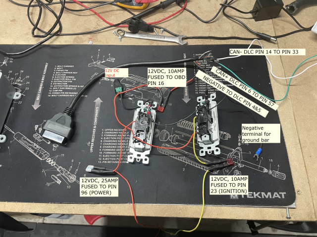
So that's what will house all of the goodies. For OBD2 connector I chose: https://www.amazon.com/dp/B07F16HC12?psc=1&ref=ppx_yo2_dt_b_product_details. So here is an image of the internals and how this was all wired together:
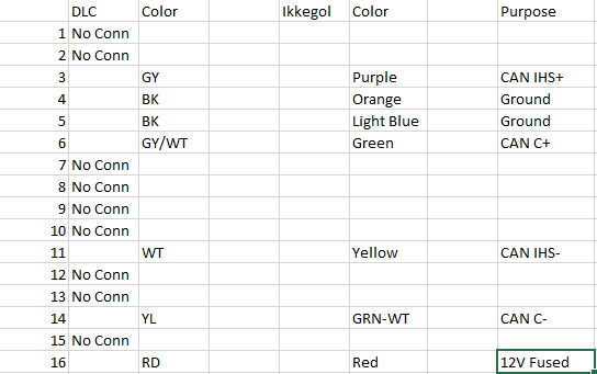
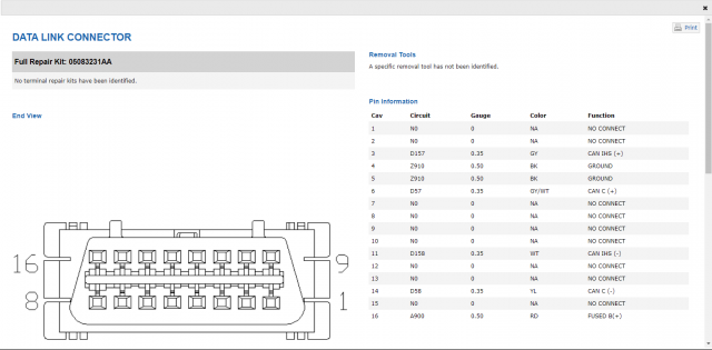
Here is my reference for the DLC connectors and the IKKEGOL harness:
Here are a bunch of foundational images that I used during my sleuthing.
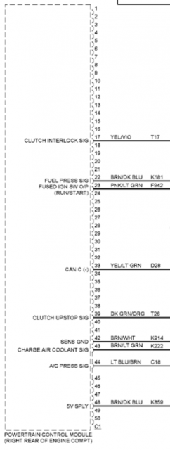
C1 pins and purposes:

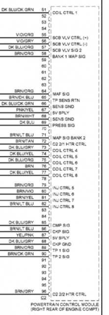
C2 Pins and purposes:

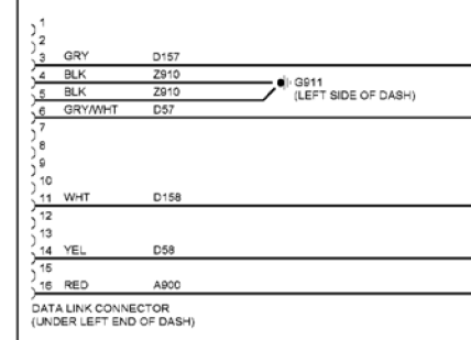
DLC:
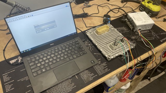
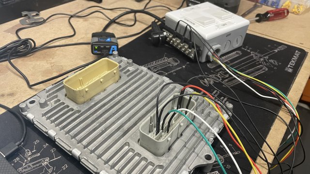
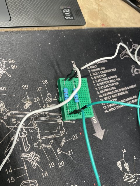
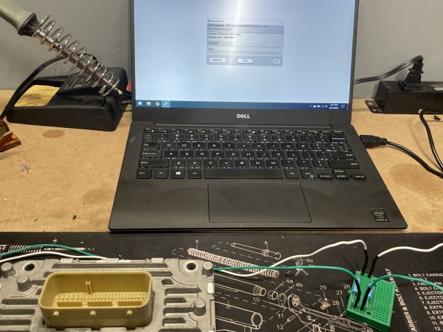
So with great pleasure I present the following:
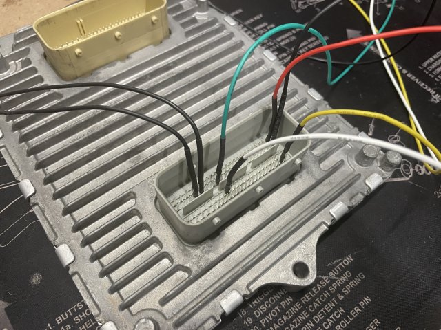
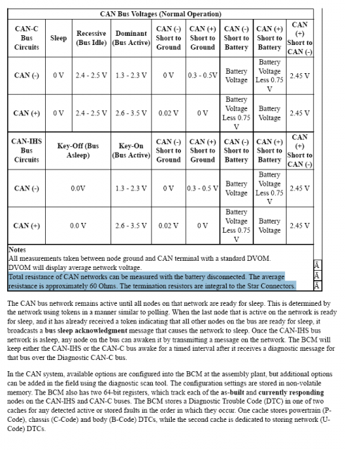
The system powers on, I can then turn on the igntion switch and all the 5v power accessories turn on. Awesome, however I do not have good CAN +/-. It feels as if the car is in ACC mode only, which makes sense as I cannot connect to it with HP Tuners when the car is in that mode as well. For CAN- I read 2.224V which means the bus is in a dominant state (bus active) and for CAN+ I read 2.825 which is dominant. Not going into the nitty gritty of CAN theory but that's akin to throwing a bunch of zeros across the line and nothing else.
If anyone knows what pin would need power to put the PCM in run mode it would be appreciated. Also can someone explain ground vs sens ground in the wiring diagrams? I'm looking forward to getting this moving forward and any help is appreciated. This is all my research done on my own and help with my electrical partner in crime @Diboblo
So that's what will house all of the goodies. For OBD2 connector I chose: https://www.amazon.com/dp/B07F16HC12?psc=1&ref=ppx_yo2_dt_b_product_details. So here is an image of the internals and how this was all wired together:

Here is my reference for the DLC connectors and the IKKEGOL harness:

Here are a bunch of foundational images that I used during my sleuthing.
C1 pins and purposes:


C2 Pins and purposes:


DLC:


So with great pleasure I present the following:

The system powers on, I can then turn on the igntion switch and all the 5v power accessories turn on. Awesome, however I do not have good CAN +/-. It feels as if the car is in ACC mode only, which makes sense as I cannot connect to it with HP Tuners when the car is in that mode as well. For CAN- I read 2.224V which means the bus is in a dominant state (bus active) and for CAN+ I read 2.825 which is dominant. Not going into the nitty gritty of CAN theory but that's akin to throwing a bunch of zeros across the line and nothing else.
If anyone knows what pin would need power to put the PCM in run mode it would be appreciated. Also can someone explain ground vs sens ground in the wiring diagrams? I'm looking forward to getting this moving forward and any help is appreciated. This is all my research done on my own and help with my electrical partner in crime @Diboblo
-
5
- Show All

